
MAE 148 - Autonomous Trash Collection Robot
Built an autonomous robot that could detect trash, drive to it, stop at the right distance, and pick it up on real hardware
I built and integrated an autonomous trash collection robot that used OAK-D Lite vision, YOLO-based detection, LD19 LiDAR stop logic, ROS2 /cmd_vel control, and a custom-mounted SO101 robotic arm. I worked on the LiDAR stop logic, arm integration, and CAD for the system, and then tested the package on the real vehicle until the sensing and control behavior lined up.
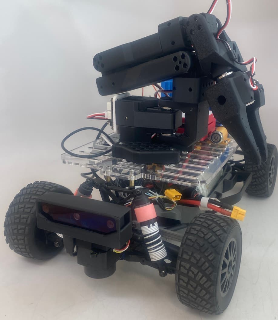


I built an autonomous robot that could detect trash, drive into a manipulation-ready pose, stop at the right distance, and hand off to an onboard arm for pickup and deposit. The stack used a YOLO-derived detector on an OAK-D Lite, ROS2 velocity control on the mobile base, and LD19 LiDAR processing for final standoff control.
The hard part was not getting one subsystem to work by itself. I had to get the sensing geometry, packaging, update rates, and mechanical layout to support the same pickup sequence on the real vehicle.
I worked on the LiDAR coding and processing, LiDAR-based stop logic, robotic arm integration, and the CAD and hardware packaging for the manipulator and sensor stack.
That meant writing and tuning the forward-cone clustering logic, choosing where sensors sat relative to the chassis and arm, and making packaging decisions that improved both reach and controllability.
- Filtered LD19 scans to a forward cone and converted clustered returns into a centroid-based stop measurement.
- Integrated the SO101 arm and mounting hardware into the vehicle package.
- Worked the sensor-placement problem so visual steering and LiDAR stopping referenced usable geometry.
The robot followed a staged reactive pipeline: OAK-D Lite detection picked the target, image-centroid error generated steering corrections, LD19 LiDAR estimated forward standoff distance, and a ROS2 node published /cmd_vel until the robot reached a manipulation-ready position.
We kept the architecture light enough for the platform. Inference ran on the OAK-D Myriad X accelerator to reduce USB load, queue depth stayed low to keep the data fresh, and the controller stayed simple enough that we could tune it on hardware.
I used forward-cone clustering instead of trying to reconstruct the full scene. I filtered returns to roughly +/-20 degrees, rejected points outside about 0.15 m to 1.50 m, grouped adjacent returns with a 0.08 m clustering threshold, and used the nearest cluster centroid as the stop signal.
The approach controller used image-centroid steering and published ROS2 /cmd_vel commands at about 10 Hz. Steering came from normalized image error, while the robot kept moving forward slowly until the centroid-based LiDAR distance reached about 0.16 m.
- OAK-D Lite plus YOLO detection for target nomination.
- Image-centroid steering for short-horizon visual alignment.
- Centroid-based LD19 stop logic for consistent arm reach setup.
The arm package was not a bolt-on subsystem. The manipulator base, camera, LiDAR, wiring, and trash bin all competed for the same deck space, so the CAD and bracket work directly affected whether the robot could see and reach the object.
I built the arm geometry around reach, visibility, and service access rather than kinematics alone. Keeping the arm on the centerline helped stability, while the forward sensor package kept a usable view of low targets during the approach phase.
Sensor placement changed control performance directly. If the camera and LiDAR axes drifted apart mechanically, the robot could center a target visually while stopping relative to the wrong physical line. That made sensor packaging part of the controls problem, not just a mounting task.
The other major constraints were USB bandwidth, compute, and power stability. We reduced camera and LiDAR rates to about 10 Hz, ran inference on-device, and kept the controller simple because the system needed to run reliably on the hardware we had.
The finished system could detect a target, follow it, stop before contact, and support arm-based collection from a coherent vehicle package.
It also gave me direct experience with the kind of robotics work I want to keep doing: CAD, sensing, wiring, ROS2 nodes, and controller tuning all coming together on a robot that actually runs.